Voltage Regulator Circuit
There are two main types of voltage regulators: linear and switching. Both types regulate a system’s voltage, but linear regulators operate with low efficiency and switching regulators operate with high efficiency. In high-efficiency switching regulators, most of the input power is transferred to the output without dissipation.

A resistor, is connected in series with the zener diode to limit the amount of current flowing through the diode and the input voltage Vin (Which must be greater than the zener voltage) is connected across as shown in the image and the output voltage Vout, is taken across the zener diode with Vout = Vz (Zener Voltage). As we know Zener diode starts conducting in reverse direction when the applied voltage is higher than the breakdown voltage of Zener. So when its start conducting, it maintains the same voltage across it and flow back the extra current, thus provide the stable output voltage.
Related: Automatic Voltage Regulator for Generator
When the switch in ON the diode remain reversed biased and power supply is connected to the inductor. When the switch is open the polarity of inductor get reverse and the diode become forward biased and connect the inductor to the ground. Then the current through the inductor decreases with slope:
The Capacitor is used to prevent the voltage from dropping to zero across the load. If we keep opening and closing switch the average voltage across the load will be less than the supplied input voltage. You can control the output voltage by varying the duty cycle of the switching device.

Voltage Regulator Circuit: Linear Regulators
Linear voltage regulators continue to enjoy widespread use despite the increasing popularity of switching approaches. Linear regulators are easily implemented, and have much better noise and drift characteristics than switchers. Additionally, they do not radiate RF, function with standard magnetics, are easily frequency compensated, and have fast response. Their largest disadvantage is inefficiency. Excess energy is dissipated as heat. This elegantly simplistic regulation mechanism pays dearly in terms of lost power. Because of this, linear regulators are associated with excessive dissipation, inefficiency, high operating temperatures and large heat sinks. While linears cannot compete with switchers in these areas they can achieve significantly better results than generally supposed. New components and some design techniques permit retention of linear regulator’s advantages while improving efficiency.
One way towards improved efficiency is to minimize the input-to-output voltage across the regulator. The smaller this term is, the lower the power loss. The minimum input/output voltage required to support regulation is referred to as the “dropout voltage.” Various design techniques and technologies offer different performance capabilities. Appendix A, “Achieving Low Dropout,” compares some approaches. Conventional three terminal linear regulators have a 3V dropout, while newer devices feature 1.5V dropout (see Appendix B, “A Low Dropout Regulator Family”) at 7.5A, decreasing to 0.05V at 100μA.
Linear regulators are step-down converters, so by definition the output voltage is always below the input voltage. However, these regulators offer a few advantages: they are generally easy to design, dependable, cost-efficient, and offer low noise as well as a low output voltage ripple.
Linear regulators are step-down converters, so by definition the output voltage is always below the input voltage. However, these regulators offer a few advantages: they are generally easy to design, dependable, cost-efficient, and offer low noise as well as a low output voltage ripple.
1. Linear Shunt Voltage Regulator
Basic circuit of a linear shunt regulator:
 |
| Shunt regulator |
The operation of the circuit can be explained as follows:
When the output voltage tries to increase because of a change in load resistance, the voltage at the noninverting terminal of the operational amplifier also increases. This voltage is compared with a reference voltage, and the resulting difference voltage causes Q1 conduction to increase. With constant Vi and Vo, IL will decrease, and Vo will remain constant. The opposite action occurs when Vo tries to decrease. The voltage appearing at the base of Q1 causes its conduction to decrease. This action offsets the attempted decrease in Vo and maintains it at an almost constant level.
To improve the power handling of the shunt transistor, one or more transistors connected in the common-emitter configuration in parallel with the load can be employed, as shown:
 |
| Linear shunt regulator with two transistors as shunt element |
2. MP2018 Linear Regulator
Linear regulators MP2018, only require an input and output capacitor to operate. Their simplicity and reliability make them intuitive and simple devices for engineers, and are often highly cost-effective. |
| MP2018 Linear Regulator |
3. Series Voltage Regulator
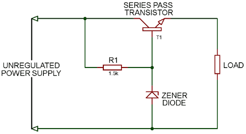
Series Voltage Regulator is a part of Linear Voltage Regulator and also called as Series Pass Regulator. A variable element connected in series, used for maintaining constant output voltage. As you change the resistance of series element voltage drop across it can be varied to ensure that the voltage across output is constant.
As you can see the circuit diagram for Series Voltage Regulator, NPN transistor T1 is the series element and a zener diode is used to provide the reference voltage.
When the output voltage increases the base-emitter voltage decreases, due to this transistor T1 conduct less. As T1 conducts less it reduce the output voltage hence maintains the output voltage constant.
When the output voltage decreases the base-emitter voltage increases, due to this transistor T1 conduct more. As T1 conducts more it increase the output voltage hence maintains the output voltage constant.
The output voltage is defined as:
VO = VZ - VBE
Where,
VO is the output voltage
VZ is Zener breakdown voltage
VBE is base-emitter voltage
4. Zener Voltage Regulator
Zener Voltage Regulators are cheaper and only suitable for low power circuits. It can be used in applications where the amount of power wasted during regulation is not of major concern.

A resistor, is connected in series with the zener diode to limit the amount of current flowing through the diode and the input voltage Vin (Which must be greater than the zener voltage) is connected across as shown in the image and the output voltage Vout, is taken across the zener diode with Vout = Vz (Zener Voltage). As we know Zener diode starts conducting in reverse direction when the applied voltage is higher than the breakdown voltage of Zener. So when its start conducting, it maintains the same voltage across it and flow back the extra current, thus provide the stable output voltage.
Related: Automatic Voltage Regulator for Generator
Voltage Regulator Circuit: Switching Voltage Regulator
There are three types of switching voltage regulator:
- Buck or Step-Down Switching Voltage Regulator
- Boost or Step-Up Switching Voltage Regulator
- Buck / Boost Switching Voltage Regulator
1. Buck or Step-Down Switching Voltage Regulator
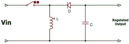
A Buck Regulator is used to step down the voltage at the output, we can even use the voltage divider circuit to reduce the output voltage but the efficiency of voltage divider circuit is low, because resistors dissipates energy as heat. We use capacitor, diode, inductor and switch in the circuit. The circuit diagram for Buck Switching Voltage Regulator is given below:
When the switch in ON the diode remain reversed biased and power supply is connected to the inductor. When the switch is open the polarity of inductor get reverse and the diode become forward biased and connect the inductor to the ground. Then the current through the inductor decreases with slope:
d IL / dt = (0-VOUT) / LThe Capacitor is used to prevent the voltage from dropping to zero across the load. If we keep opening and closing switch the average voltage across the load will be less than the supplied input voltage. You can control the output voltage by varying the duty cycle of the switching device.
Output Voltage = (Input Voltage) * (percentage of time that the switch is ON)2. Boost or Step-Up Switching Voltage Regulator
The Boost Regulator is used to step-up the voltage across the load. The circuit diagram for boost regulator is given below:

When the switch is closed the diode behaves as reversed biased and the current across the inductor keeps increasing. Now when the switch is opened, the inductor will create a force causing the current to continue flowing and capacitor starts charging. By continuous turning the switch ON and OFF we will receive the voltage at the load higher than the input voltage. We can control the output voltage by controlling the turn ON (Ton) time of the switch.
Output Voltage = Input Voltage / Percentage of time that the switch is open3. Buck-Boost Switching Voltage Regulator
Buck-Boost Switching Regulator is the combination of both Buck and Boost Regulator, it gives inverted output which can be greater or less than the supplied input voltage.
When the switch is ON the diode behaves as reversed biased and inductor stores energy and when the switch is OFF inductor start releasing the energy with the reverse polarity, which charges the capacitor. When the energy stored in inductor becomes zero the capacitor starts discharging into the load with reverse polarity. Due to this buck-boost regulator also called as inverting regulator.
The output voltage is defined as
Vout = Vin (D / 1-D)
Where, D is the Duty cycle
Hence, if the Duty Cycle is low the regulator behaves as the Buck Regulator and when the Duty Cycle is high the regulator behaves as the Boost Regulator.
Gift for you: Practical Example
۞ Generate electricity to power your home with just a battery or phone charger
۞ The Square Pulse Generator controls the power generation on demand
❉ Free Energy from Nikola Tesla's friend: Alfred M. Hubbard's Free Energy Transformer | Charge your phone to power your home! A step-by-step guide to making a "Free Energy Transformer" by Alfred M. HUBBARD | Ether Technology was suppressed in the 1920s
❉ How to make free electricity simpler for anyone: Free Energy Transformer
Revealed At Last: Ancient Invention Generates Energy-On-Demand

✔ Nikola Tesla’s method of magnifying electric power by neutralizing the magnetic counter-forces in an electric generator

Generates Energy-On-Demand: Easy Power Plan Will Change Our World Forever
✔ Combination of induction motor and alternator
✔ Combine generators with induction motors - self-powered generators with rotary motion
✔ Various methods of generating high power immobile generators
✔ Or maybe called Overunity for the system. Mother Nature doesn't care about people calling or naming phenomena. Overunity or Free Energy, or Zero Point Energy (ZPE) are just a few different words
Linear and Switching Regulator Applications
Linear regulators are often used in applications that are cost-sensitive, noise-sensitive, low-current, or space constrained. Some examples include consumer electronics such as headphones, wearables, and Internet-of-Things (IoT) devices. For instance, applications such as a hearing aid could use a linear regulator because they don’t have a switching element that could create unwanted noise and interfere with the device’s performance. Moreover, if designers are mainly interested in creating a low-cost application, they need not be as concerned with power dissipation, and can rely on a linear regulator. Switching regulators are beneficial for more general applications, and are especially useful in applications that need efficiency and performance, such as consumer, industrial, enterprise, and automotive applications. |
| MPQ4430-AEC1 Step-Down Regulator |
For example, if the application requires a large step-down solution, a switching regulator is better suited, since a linear regulator could create high power dissipation that would damage other electrical components.


Post a Comment